Rotational Capacity Test Overview
The Rotational Capacity test’s main purpose to test A325 & A490 high-strength bolt, nut & washer, as an assembly, to show the presence of lubrication, on galvanized nuts. The Rotational Capacity test or RC test can also test the assembly’s strength (tension,) ductility, and thread strength (threads resistance to strip.) To preform a RC test, you will need of 2 sets of, a specific combination of bolt, nut & washer, a bolt tension testing device, as well as a . These 2 sets of bolt, nut & washer(s) will consist of the same lot numbers for the bolt, nut & washer, which will match the lot number for the bolt, nut & washer(s) used in the connections of the actual steel members, in the structure. Each set of bolt, nut & washer will be given it’s own Rotational Capacity Test Lot # or RC # and should be marked as being part of that RC # on the kegs for easy identification of said RC assembly components. If you change one of the components of the RC assembly, you will have to preform a new RC test with a separate RC #. The Rotational Capacity test is usually required for most bridge projects under AASHTO’s Standard Specifications for Highway Bridges and Bridge Construction Specifications for both A325/A490 bolts, as well as contract documents for local, State DOT’s, FHWA, etc. This test is in addition to the pre-installation verification testing for the installation method.
10. Rotational Capacity Test Methods
10.2 Rotational Capacity — The zinc-coated bolt shall be placed in a steel joint or tension measuring device and assembled with a zinc-coated washer and a zinc-coated and lubricated nut with which the bolt is intended to be used (see Note 4). The nut shall have been provided with the lubricant described in the last paragraph of the Manufacturing Processes section of Specification A563. The joint shall be one or more flat structural steel plates or fixture stack up with a total thickness, including the washer, such that 3 to 5 full threads of the bolt are located between the bearing surfaces of the bolt head and nut. The hole in the joint shall have the same nominal diameter as the hole in the washer. The initial tightening of the nut shall produce a load in the bolt not less than 10 % of the specified proof load. After initial tightening, the nut position shall be marked relative to the bolt, and the rotation shown in Table 6 shall be applied. During rotation, the bolt head shall be restrained from turning. After the tightening rotation has been applied, the assembly shall be taken apart and examined for compliance with 6.3.3.
NOTE 4—Rotational capacity tests shall apply only to matched assembly lots that contain one A325 bolt, one A563 lubricated nut, and one F436 washer that have been zinc coated in accordance with either Specifications F2329 or B695. Both the bolt and nut components of the matched assembly shall be zinc coated using the same process.
Procedure
1. Take two assemblies from the rotational-capacity lot. The rotational-capacity (RC) lot is designated as the A325 or A490 bolt production lot, assembled with the provided A563 nuts, of corresponding diameter and recorded production lot number, and the provided F436 washers, of the corresponding diameter and production lot number. Note: Bolts are measured from under the head to the end of the shank.
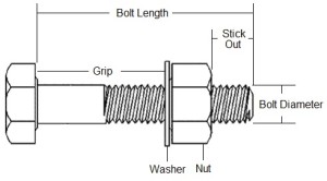 2. Install an assembly in a bolt tension calibration device so that between three and five threads are in the grip (the area between the underside of the bolt head and the washer.) Use hardened spacer bushings or steel shim plates as required, to have full thread engagement of bolt threads with the end of the nut, DO NOT “STACK OUT” WASHERS. No more than 2 F436 washers should ever be used when preforming a Rotational Capacity Test. Some bolts barely fit into the device, all you need is to make sure the end of the bolt is at least flush with the outer face of the nut, IE full thread engagement. Make sure the RC lot washer (if a washer is used) is placed directly beneath the nut. Note: if no washer is required in the actual connection of the steel members, the test should still be conducted using an F436 washer of the proper diameter.
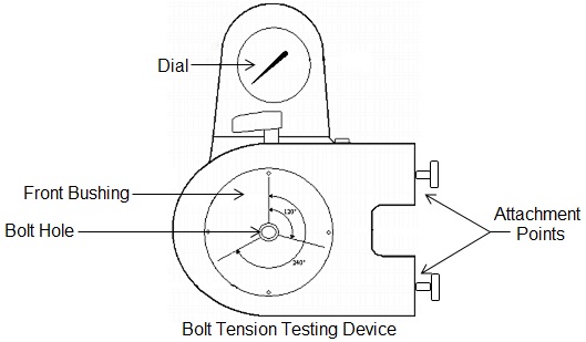
3. Snug the joint by hand or with a wrench to a low level of initial tension, in order to start the test at the correct point. This tension should not exceed the following tensions, with a tolerance of +2, -0 kips:
Maximum Initial Tension Chart
| Bolt Diameter | A325/F1852 | A490/F2280 |
|---|---|---|
| 1/2 | 1000 | 2000 |
| 5/8 | 2000 | 2000 |
| 3/4 | 3000 | 4000 |
| 7/8 | 4000 | 5000 |
| 1 | 5000 | 6000 |
| 1-1/8 | 6000 | 8000 |
| 1-1/4 | 7000 | 10000 |
| 1-3/8 | 9000 | 12000 |
| 1-1/2 | 10000 | 15000 |
| Source: FHWA Appendix A1 | ||
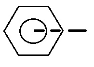
4. Match mark the bolt end, nut and bolt tension calibrator face-plate with a straight line. Match marking ensures that the bolt is not turning while you’re rotating the turning element. Match marking should look something like the below diagram:
5. Tighten the bolt to at least the pretension listed below and record both the tension and torque.
Installed Minimum Tension
| Bolt Diameter | A325/F1852 | A490/F2280 |
|---|---|---|
| 1/2 | 12,000 | 15,000 |
| 5/8 | 19,000 | 24,000 |
| 3/1 | 28,000 | 35,000 |
| 7/8 | 39,000 | 49,000 |
| 1 | 51,000 | 64,000 |
| 1-1/8 | 56,000 | 80,000 |
| 1-1/4 | 71,000 | 102,000 |
| 1-3/8 | 85,000 | 121,000 |
| 1-1/2 | 103,000 | 148,000 |
| Source: FHWA Appendix A1 | ||
To measure torque it is necessary to rotate the nut an additional 5 degrees. This torque value must not exceed the following calculated value:
T = 0.25 * P * D
T = Maximum permitted torque, in ft-lbs
P = Bolt tension, in pounds
D = bolt Diameter, in feet
Maximum Torque At Installed Tension
| Diameter | A325 | A490 |
|---|---|---|
| 1/2" | 125 | 156 |
| 5/8" | 247 | 312 |
| 3/4" | 434 | 546 |
| 7/8" | 712 | 893 |
| 1" | 1071 | 1333 |
| 1-1/8" | 1313 | 1875 |
| 1-1/4" | 1849 | 2657 |
| 1-3/8" | 2435 | 3467 |
| 1-1/2" | 3219 | 4675 |
| Source: T = 0.25 * P * D | ||
6. Further tighten the bolt until the rotation reaches the total rotation as show in the following table. This rotation is measured from the initial match mark made in step 4. The bolt length for this table is measured from the underside of the bolt head to the end of the bolt shank.
Required Degrees of Rotation by Bolt Length
| Bolt Length (L) | Rotaion Required |
|---|---|
| L ≤ 4 X Bolt Dia | 240 ° or 2/3 rds turn |
| > 4 ≤ 8 X Bolt Dia | 360 ° or 1 Full Turn |
| >8 X < 12 X Bolt Dia | 420 ° or 1-1/6 Turn |
| Source: FHWA Appendix A1 - A325 Preforming Rotational Capacity Test Long Bolts in Tension Calibrator | |
7. The tension at final rotation must be equal to or greater than (1.15 * the installed minimum tension, chart from step 3). Use the chart below as a quick reference for the aforementioned formula.
Tension at Final Rotation
| Diameter | A325 kips | A490 kips |
|---|---|---|
| 1/2" | 14,000 | 17,000 |
| 5/8" | 22,000 | 28,000 |
| 3/4" | 32,000 | 40,000 |
| 7/8" | 45,000 | 56,000 |
| 1" | 59,000 | 74,000 |
| 1-1/8" | 64,000 | 92,000 |
| 1-1/4" | 82,000 | 117,000 |
| 1-3/8" | 98,000 | 139,000 |
| 1-1/2" | 118,000 | 170,000 |
| Source: 1.15 * the installed minimum tension | ||
8. Remove the assembly from the test device. Inspect the bolt threads and nut threads for indications of thread stripping or thread shearing. Also check for signs of torsional or tensile failure (cracks) of the bolt. Stretching of the threads is to be expected and is acceptable. If stripping, shearing or other failure is noted, the assembly fails the test.
9. Repeat the RC test as described in Steps 2 – 9. Record the results on an appropriate form, be sure to include component production lot numbers, and the RC lot number as provided.
Failure/Rejection
The following constitute a failure of the rotational capacity test:
- Exceeding the maximum allowable torque.
- Failure to achieve the required degrees of rotation.
- Failure to achieve the required tension at the required rotation.
- Thread failure
You should expect to see some stretching in the threads, which is normal due to the ductility of A325 bolts, comparably A490 are less ductile. You should be able to run the nut up the threads to the point at which the bolt shank stretched.
If you have a RC Assembly that FAILS: Most DOT’s, FHWA or interested parties have a clause that states something along the lines of, “Upon failure the contractor is given the option to clean or re-lube (hex bolts only) and retest. Upon second failure, the Rotational Capacity Lot is rejected.” Read your documentation and be aware of possible corrective methods, in advance of testing.
Sources: ASSTHO, ASTM, FHWA, & RCSC